18 - 18th Edition - RCDs Mode 3 EV Charging
Mode 3 Charging: RCDs – Considerations for Installation Approval
Mode 1 and 2 charging were never intended to provide permanent solutions for charging Electric Vehicles. The in-cable control box (ICCB) built into a mode 2 charging cable, provides some protection for certain faults. Any cable supplied with a 13A plug still relies on integrity of the 13A supply that it is connected to, even where the charging current is limited to 8 or 10A for the duration of the charge. Consequently, the standards consider Mode 2 charging to be a temporary or emergency solution, where Mod 3 infrastructure is not available.
Providing correctly engineered Mode 3 charging infrastructure in accordance with section 722 of the 18th Edition, is the minimum requirement detailed in the OLEV Technical Specification for EV charging infrastructure. For sites where employees, customers or members of the public may charge their EVs using their own charging cables, the risks must be properly managed by those responsible for site safety e.g. an employ would not be allowed to use their own electric kettle on site, without any testing of the apparatus first.
Wiring Regulations take precedence over any existing standards
The Government’s minimum technical specification for EV charge points states “In cases of apparent inconsistency in installation requirements, the IET Wiring Regulations (BS 7671) shall take precedence” i.e. the existing version of BSEN 61851-1* does not include the 18th Edition requirements. If you are intending to use Type A RCDs for Mode 3 charging, Reg 722.531.2.101 requires the provision of measures for protection against dc fault currents, either separately (externally) or included in the chargepoint.
* Note: The bsi site refers to BSEN61851-1 as replaced by BSEN 62752 which relates to IC-CPDs for Mode 2 charging cables! Not related to this revision in the Regulations. The 18th Edition requirements are covered in IEC 61851-1 February 2017 and IEC 62955 published in March 2018. IEC 62955 (BS IEC 62955) deals with RDC-DDs (Residual direct current detecting device) for use in Mode 3 charging applications as referred to in IEC 61851-1 2017.
- Check that the equipment you are intending to install meets the latest IEC standards: Does the EV charge point specification make refence to IEC 61851-1 February 2017 (check the date on the Manufacturers documentation and the D of C ). See Reg 133.1.1
- EV Equipment manufactured to BSEN61851-1: Refer to the manufacture for advice and recommendations before installing. See Reg 133.1.3 e.g. Tesla specify the use of a Type A RCCB to meet IEC61851-1 2017
- Understanding the associated terminology: Do not confuse, devices designed for “detecting and monitoring” residual currents with devices suitable for “residual current protection” - see note in Reg 411.1 and the required standards for RCD protection devices listed at the end of Reg 722.531.2.101
Associated Terminology
An RCD, under specified fault conditions must disconnect and “isolate” the circuit. Conversely, a contactor controlled by an RCM can disconnect a circuit, but it does not provide isolation. RDC-DD is a new term associated with devices suitable for the detection of 6 mA DC in Mode 3 charging. The standard proposes various formats - see below.
RCD: Generic term for a device providing for example 30 mA residual current protection and isolation. It must meet one or more of the following EN / IEC standards; 61008-1, 61009-1, 60947-2 or 62423.
RCM: A device that monitors residual currents but does not provide protection, not to be confused with the requirements for the detection of 6 mA DC fault currents as specified in IEC 62955 for Mode 3 charging.
RDC-DD: Generic term for an RDC-M device providing 6 mA DC fault current disconnection for Mode 3 charging applications with a separate Type A RCD providing protection - see Table 1.
RDC-PD: A device that incorporates 6 mA DC monitoring, detection and 30 mA Type A residual current protection in one unit.This table summarises the various RDC formats proposed in IEC 62955 relating to the revised requirements in IEC 61851-1 February 2017, for inclusion by the EV charge point manufacturer.
| Clause | Function | Description |
|---|---|---|
| 4.1.1.1 | Monitoring 6 mA DC | RDC-MD with mechanical switching in one unit To be connected in series with 30 mA Type A RCD for protection. |
| 4.1.1.2 | Monitoring 6 mA DC | RDC-MD-UNIT mechanically coupled to a separate protective device If the protective device is an MCB, a separate 30 mA Type A RCD must be connected in series with the MCB. |
| 4.1.1.3 | Monitoring 6 mA DC | RDC-MD-MODULE electrically coupled to a separate remotely operated switching or protective device. If the switching device is a contactor, relay or MCB, a separate RCD must be connected in series. |
| 4.1.1.4 | Protection 6 mA DC + 30mA AC | RDC-PD-Combined Protection, Monitoring and Isolation device Integrated AC, pulsating DC and 6 mA DC detection evaluation and isolation in one device. |
Table 1. IEC62955 Classification of RDC-DD (RDC-MD, RDC-PD) for Mode 3 charging
Application Notes:
RCMs and RDC-DDs can only be incorporated in the EV chargepoint by the original manufacturer, as part of the monitoring and control system. The relevant standards define the tests required to prove discrimination between the RCM or RDC-DD and the separate RCD required for 30 mA protection – see inspection & testing next.
IEC 62955 clause 8.11 Note 2 states that “Additional requirements and testing procedure for testing the performance manually or automatically are under consideration”. New standards are subject to change, as the practicalities of implementing new requirements and recommendations become clearer.
Installation Inspection & Testing
If there is a disagreement between the Installer and the Chargepoint Manufacturer on interpretation of the Wiring Regulations, legally the installation cannot be signed off and put into service.
Unlike a credit agreement, there is no cooling -off period when you sign an Installation Certificate. A copy of this Certificate will be held on record by the Government for future reference.
e.g. for Home Charge scheme, see Section 2 B - Quote “The installation is in accordance with the current edition of the Building Regulations Part P (Electrical Safety – Dwellings) and in full compliance with the requirements of the current edition of the UK wiring regulations (BS7671) and the IET Code of Practice for Electric Vehicle Charging Equipment Installation and that I can provide all evidence required of compliance with these documents, as specified by them.”
Inspection - Regulation 642 and Functional Testing – Regulation 643.10
See Regulations 113.1, 133.1.1, 511.1, 511.2: At the time of writing, the current versions of BSEN standards relating to Mode 3 charging, do not cover the requirements in Reg. 722.531.2.101, relating to the use Type A RCDs. Regulation 133.1.1 requires that in the absence of an appropriate standard, reference shall be made to the IEC standard i.e. IEC 61851-1 2017 and BS IEC62955 2018 until the revised BSEN standards are published.
Charge Point Manufacturer & Installer have a joint responsibility and must agree on the following: Where measures for additional protection rely on the interaction of the RDC-MD, supplied in the charge point and a separate RCD either mounted in the charge point or remotely, agreement must be reached on the minimum number of tests and any supporting documentation required to prove compliance with Regulation 536.3 … the mutual interaction between those devices shall be considered so that they do not adversely affect the safety of the installation .. including residual currents … and selectivity. Explained below.
Regulation 643.8 only covers the verific ation by testing of the RCD in a simple installation such as a domestic ring main.
Functional Testing – Regulation 643.10: An EV charge point supplied with an RDC-MD + Contactor for 6 mA DC disconnection and a separate 30 mA Type A RCD for protection, must be coordinated to achieve selectivity under given residual current conditions – see Regulation 536.3. To achieve selectivity as defined in regulation 536, functional tests and documentation will demonstrate that: In the presences of AC residual current, the RCD must trip for effective circuit isolation.
- The RDC-MD + Contactor disconnects the circuit in the presence of a smooth dc residual current
- The RDC-MD + Contactor and RCD do not trip at 15 mA (0.5 x I∆n)
- The RCD will trip < 40 ms @ 150 mA (5 x I∆n) and < 300 ms @ 30 mA (1 x I∆n)
- For AC residual currents: RDC-MD + Contactor must not operate before the RCD
IEC62955 / RDC-MD: Table 2 specifies maximum break times for DC fault currents and Table 3 specifies non-operating times, when subjected to AC residual currents.
DC residual currents: RDC-MD must disconnect the supply, to maintain the integrity of the 30mA AC protection - see Table 2.
AC residual currents: For protection, the RDC-MD must not operate before the RCD – see Table 3.
| Standard values of maximum break times at a residual direct current equal to | ||
|---|---|---|
| 6 mA | 60 mA | 200 mA |
| 10s | 0.3s | 0.1s |
Table 2 (IEC 62955)
Note: RDC-MD non-operating current is 0.5 I∆dc
| Minimum values of non-operating time (in seconds) in the event of alternating residual currents (RMS values) equal to | |||
|---|---|---|---|
| Up to 30mA | 60 mA | 150 mA | 5 A |
| No tripping | 0.3 | 0.08 | 0.08 |
Table 3 (IEC 62955)
Note: RDC-MD non-operating current is 0.5 I∆dc
Note: Table 3 only applies to RDC-MD where relay or contactor contacts are used for 6 mA DC switching and a separate RCD provides the fault switching and isolation function. (RDC-PD switching, and isolation function performed by the same contacts. The RDC-PD must conform to the RCCB or RCBO standards).
Quick safe and simple solution
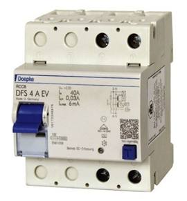
As an example, Tesla already recommend the use of a 30 mA Type A-EV RCCB with their Mode 3 charge points, to provide disconnection of the supply in case of DC fault current above 6 mA. This ensures that the circuit is effectively isolated under fault conditions, and that any upstream Type A RCDs are isolated from the effects of DC fault currents, meeting the requirements of IEC 61851-1 2017. Simple to install and test.
Keep-up-to-date
This article is based on available information1. Manufacturers & Installers must carry out their own risk assessments of Product Design, Product Safety Reviews and Installation Practices to meet the requirements of existing Legislation. Manufacturers and Importers should have robust product safety review processes, enabling them to change and adapt quickly to cover design weakness. Keeping in mind that the State of the Art and Issues of Safety generally drive standards in evolving markets.
Check with the various associated Trade Bodies, IET and Standards Organisations to keep up-to- date with the subjects covered in this article. In the absence of clearly defined requirements, the Manufacture of the charge point and the Responsible Person for testing and signing off the installation, will need to agree what tests are required to verify that the installation is safe for use.
Chaz Andrews – Technical Manager, Doepke UK Ltd
1Information available in the Public Domain as of 1st Oct 18
SOURCE: © 2018 - 2025 Chaz Andrews. All Rights Reserved. Doepke Tec Art 18 RCDs Mode 3 Applications_ 18th Edition v2 Jan19